Modbus RTU Fuji Alpha 5 with Omron NB10
Application
- Control Fuji
Alpha 5Servo Motor with OmronNB10HMI. Servo OnandRunwould be controlled from PLC with Digital IO.- Setting of Speed and Monitoring from HMI
- PLC outputs are
NPN.
Electrical Wiring
Three types of of Wirings
- High Voltage wiring for
Servo Drive, Servo drive to motor with prefabricated Cables from Fuji. - Digital control Wiring between Drive
IO ConnectorandPLC. - Low voltage wiring for
HMI - Communication Cable between
Servo DriveandHMI - Communication Cable between
PC LoaderandDrive
Drive and Motor Wiring
- Connect
220V ACtoL1andL2on the Drive. - Connect
U, V, Won the drive to Motor Power Connector. Encodercable from DriveCN2port to Motor Encoder.
Control Wiring
Fuji Alpha 5 has IO connector on CN1 port.
CN2 IO Cable
| Pin No | Terminal symbol | COLOUR |
|---|---|---|
| 1 | COM IN | Red |
| 2 | CONT1 | Brown |
| 3 | CONT2 | Green |
| 4 | CONT3 | Violet |
| 7 | CA | Blue |
| 8 | *CA | Black |
| 14 | COM OUT | White |
| 15 | OUT1 | Gray |
| 19 | PPI | Pink |
| 6 | M5 | Yellow |
Follow the bellow wiring
- Connect
RedWireCOM INto24 VDC - Connect
BrownWireCONT1toPLC OutputforServo ON - Connect
GreenWireCONT2toPLC OutputforServo Run
Communication Wiring Drive to HMI
Fuji Alpha 5 has RJ45 with port CN 3A (IN) to NB HMI COM2 DB9 Connector
RJ45 Connector with Cat 6 cable on Drive Side
| Pin No | Cable Color |
|---|---|
| 3 | White/Orange |
| 4 | Brown |
| 5 | White/Brown |
| 6 | Orange |
9 Pin Connector on HMI Side
| Pin No | Cable Color |
|---|---|
| 6 | White/Orange, White/Brown |
| 8 | Brown, Orange |
Communication Wiring Drive to Drive
Fuji Alpha 5 has RJ45 with port CN 3B (OUT) to Fuji Alpha 5 has RJ45 with port CN 3A (IN)
| Pin No | CN 3B (OUT) | CN 3A (IN) |
|---|---|---|
| 1 | Blue | Blue |
| 2 | White/Blue | White/Blue |
| 3 | White/Orange | White/Orange |
| 4 | Brown | Brown |
| 5 | White/Brown | White/Brown |
| 6 | Orange | Orange |
| 7 | White/Green | White/Green |
| 8 | Green | Green |
Communication Wiring Drive to PC Loader
Connect Programming PC with USB to RS422/485 Converter
| Pin No | CN 3A (IN) |
|---|---|
| 3 | T/R + |
| 4 | T/R - |
| 5 | T/R + |
| 6 | T/R - |
Parameters
- Parameter
PA3:01to1for SettingCONT1Signal asServo ON. - Parameter
PA3:02to2for SettingCONT2Signal asServo RuninForwarddirection. - Parameter
PA3:02to3for SettingCONT2Signal asServo RuninReversedirection.
To change the direction without modifying CONT2 parameter, Set PA3:02 to 2 and set PA1:04 to 0 for CCW or 1 for CW.
HMI Program
- Create a New project in
NB-Designerand Select correct HMI Model fromPTinProject Library Window. - In
PLCtab ofProject Library Window, SelectModbus RTU Extended. - Set Station Number same as Node address of the
Fuji Drive - From
Connectorstab, selectSerial Portand connect drive and HMI.
Speed Change
To set speed from HMI, Create a Number Input Property. Set properties as below,
| Property | Value |
|---|---|
| PT | HMI0 |
| PLC NO | 0 |
| Port | COM2 |
| Station | 1 |
| Area | 4X-DINV |
| Address | 16425 |
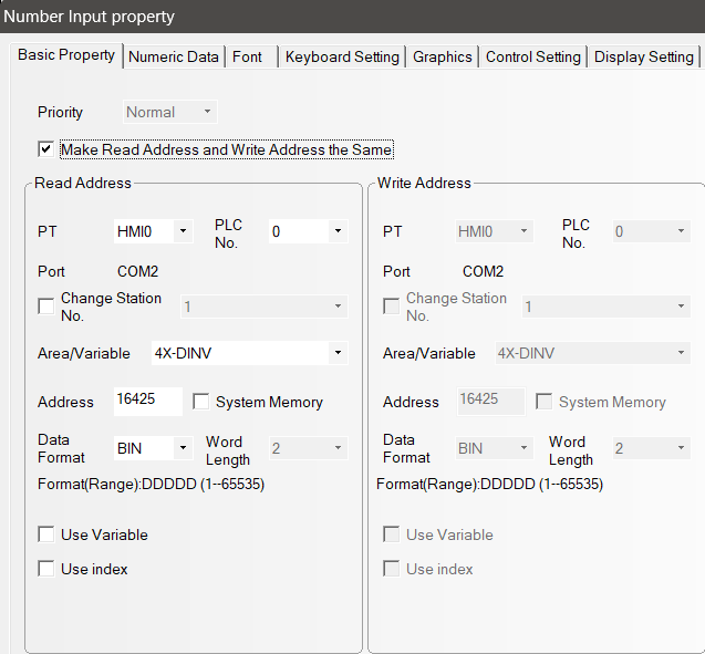
Change Station Number based on the Node address of the Drive.
Parameter PA2:72
Speed Monitor
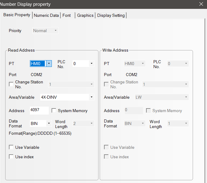
To set speed from HMI, Create a Number Display Property. Set properties as below,
| Property | Value |
|---|---|
| PT | HMI0 |
| PLC NO | 0 |
| Port | COM2 |
| Station | 1 |
| Area | 4X-DINV |
| Address | 4097 |
Please refer to Official Document for more details.